基础篇 - IPv6

系列文章,更多相关文章请移步这里

前言

IPv6 (Internet Protocol Version 6) 的出现主要是因为 IPv4 Address 供不应求。

由于 IPv4 Address 长度为 32 Bits,最多只能提供 $2^{32}$ 即大约 42 亿个 IP Address, 而地球人口达到 75 亿,虽然当中只有不足 50% 人口能使用到网络,但试想我们每人都手持超过一台可上网设备,IP Address 供应已经十分紧张,现时只能用 NAT 暂缓 IP 供应不足的问题。

IPv6 把 IP Address 长度大幅提升至 128 Bits,所能提供的 IP Address 达到天文数字。

究竟有多少呢?给大家一个概念,如果每秒钟要新增 1 兆个 IPv6 Address,IPv6 Address 数量足够使用 1 兆年以上。

** 本篇假设读者已充份了解 IPv4 的理论。**

IPv6 表示方式

16 进制

由于 128 Bits 的 IPv6 Address 实在太长,因此会把 IPv6 Address 每 4 Bits 组合起来转换成 16 进制,每 4 个 16 进数再以冒号分隔成 8 节。例如:2001:0000:0001:00a0:0000:0000:0000:0ec3

省略 0

每节起始的零可以省略,直至该节的起始不是 0 或该节只剩余 1 个 0

第 1 节 第 2 节 第 3 节 第 4 节 第 5 节 第 6 节 第 7 节 第 8 节
省略前 2001 0000 0001 00a2 0000 0000 0000 0ec3
省略后 2001 0 1 a2 0 0 0 ec3

省略前 2001:0000:0001:00a2:0000:0000:0000:0ec3
省略后 2001:0:1:a2:0:0:0:ec3

双冒号代替连续的 0

最后可以用双冒号取代一组连续出现的 0,由于只限取代一组,选最长的一段性价比较高,当然你也可以选较短的一段。

例如:2001:0:1:a2:0:0:0:ec3

可写成:2001:0:1:a2::ec3

Prefix 与 Interface ID

Router 用 Prefix 来判断 IPv6 Address 是否位于同一网络,演算法与 IPv4 Subnet Mask 相似,不在此详述,有兴趣可参考 IPv4 文章。

比较普遍的做法是把 128 Bits 长度的 IPv6 Address 分成 64 Bits 的 Prefix 和 64 Bits 的 Interface ID,Prefix 长度的表示方法是在 IPv6 Address 后加上 /xx,例如:FE80::1/642001:db8::10/64 等。

如果我们把所有 IPv6 Address 都用于 64 Bits Prefix 的网络,我们便可使用 $2^{64}$ 个网络,每个网络可以容纳 $2^{64}$ 个 Host,两者都是天文数字,因此 IPv6 很少会再把 Network 分成 Subnet。

EUI-64

IPv6 Address 太长,要网络管理人员逐个 Interface 设定 IPv6 Address 肯定是件痛苦的事。

EUI-64 让我们只需帮 Interface 设定 Prefix 部份,然后 Interface 就会用 MAC Address 自动产生 Interface ID,基于 MAC Address 独一无二,利用 EUI-64 必能生成独一无二的 IPv6 Address。

EUI-64 产生 Interface ID 的办法是先把 MAC Address (共 48 Bits) 斩开两等份,中间插入 FFFE (共 16 Bits),使其成为 64 Bits,然后把第 7 Bit 由 0 改成 1。最后在前面加上 Prefix 就成为一组 IPv6 Address 了。

举例,MAC Address:00:50:56:C1:A0:E8

中间插入 FFFE 使其成为 EUI-64 Interface ID:0050:56FF:FEC1:A0E8

最后把第 7 Bit 改成 1:2050:56FF:FEC1:A0E8

IPv6 Address 有一些预先协定的起始位,提供相应的用途,有点类似 IPv4 中的 Class 概念。

先要介绍的是首 10 Bits 为 1111111010 称为 Link-Local Address,只能给本机 Interface 与相邻设备的 Interface 作通信之用,任何 Router 都不会为 Link-Local Address 作出路由发布。

为了方便,通常会使用 FE80::/10 来表示。

设定 Link-Local Address 方法如下。

R1
1
R1(config-if)#ipv6 address fe80::1234 link-local

也可使用 EUI-64 自动产生,用以下命令就可以了。

R1
1
R1(config-if)#ipv6 enable

BTW,如要 Ping Link-Local Address 必需指定 Output Interface。

R1
1
2
3
4
5
6
7
R1#ping FE80::C802:AFF:FE4D:1C
Output Interface: Ethernet1/0
Type escape sequence to abort.
Sending 5, 100-byte ICMP Echos to FE80::C802:AFF:FE4D:1C, timeout is 2 seconds:
Packet sent with a source address of FE80::C801:AFF:FE3E:1C%Ethernet1/0
!!!!!
Success rate is 100 percent (5/5), round-trip min/avg/max = 8/16/24 ms

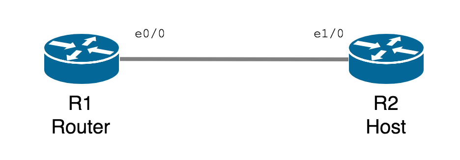
两个相连的设备设定好 IPv6 Address 后,会自动成为 IPv6 Neighbor。

IPv6 并没有 ARP 机制,IPv6 Neighbor 提供相邻设备 MAC Address。

R1
1
2
3
R1#show ipv6 neighbors
IPv6 Address Age Link-layer Addr State Interface
FE80::C802:AFF:FE4D:1C 1 ca02.0a4d.001c STALE Et1/0

Unique Local Address

首 10 Bits 是 1111110000 (或写作 FC00::/10) 称为 Unique Local Address。

Unique Local Address 像是 IPv4 中的 Private Address (10.0.0.0/8172.16.0.0/12192.168.0.0/16),在 Internet 上不可被路由,然而我们可以在自己的私有网络中使用并路由这些 IP。

Private Address 在 IPv4 中被广泛使用在 NAT 去弥补 IPv4 的 IP Address 不足问题。而 IPv6 有非常充裕的 IP 空间,因此 Unique Local Address 通常只用在测试环境。

设定 Unique Local Address 方法如下。

R1
1
R1(config-if)#ipv6 address FC00::4321/64

也可使用 EUI-64 自动产生。

R1
1
R1(config-if)#ipv6 address FC00::/64 eui-64

Global Aggregatable Address

首 3 Bits 是 001 (或写作 2000::/3) 称为 Global Aggregatable Address。Global Aggregatable Address 就昰网络上最常用的 IPv6 Address,相对于 IPv4 的 Public Address。设定方法与 Unique Local Address 相同。

当中 2002::/16 特别用作 6to4 Tunnel,本文稍后会说明。

R1
1
R1(config-if)#ipv6 address 2001::ABCD/64

使用 EUI-64 自动产生。

R1
1
R1(config-if)#ipv6 address 2001::/64 eui-64

Stateless Address Autoconfiguration (SLAAC)

在 IPv4 中我们可以通过 DHCP 让 Interface 自动获取 IP Address,而在 IPv6 则通过 Auto-configuration 来获取 IP Address。之前的部份说过 EUI-64 可以帮我们自动产生 Interface ID,所以现在解决的就是如何获取 Prefix 的问题

IPv6 用的是 Stateless Address Autoconfiguration (无状态地址自动配置),Interface 向 Link-Local 发出 RS (Router Solicitation),IPv6 Router 可以回应 RA (Router Advertisement),提供 Prefix 信息。

现在尝试把 R1 设定为 Router,R2 则尝试通过 SLAAC 获取 IP Address。

先在 R2 的 Interface 启用 IPv6,让它有 Link-Local Address。

R2
1
2
R2(config)#int ethernet 1/0
R2(config-if)#ipv6 enable

在 R1 设定 IPv6 Address。

R1
1
2
3
4
5
6
7
8
9
R1(config)#int ethernet 1/0
R1(config-if)#ipv6 address 2001::/64 eui-64
R1(config-if)#exit
R1#show ipv6 interface ethernet 1/0
Ethernet1/0 is up, line protocol is up
IPv6 is enabled, link-local address is FE80::C801:14FF:FE6F:1C
No Virtual link-local address(es):
Global unicast address(es):
2001::C801:14FF:FE6F:1C, subnet is 2001::/64 [EUI]

在 R1 启动 IPv6 Routing,使其成为 IPv6 Router,这样当它收到 RS 便会回复 RA。

R1
1
R1(config)#ipv6 unicast-routing

现在 R2 可以通过 Auto-configuration 取得 IPv6 Address 了,Prefix 是通过 R1 传来的 2001::/64

R2
1
2
3
4
5
6
7
8
9
R2(config-if)#ipv6 address autoconfig
R2(config-if)#exit
R2#show ipv6 interface ethernet 1/0
Ethernet1/0 is up, line protocol is up
IPv6 is enabled, link-local address is FE80::C802:14FF:FE7E:1C
No Virtual link-local address(es):
Stateless address autoconfig enabled
Global unicast address(es):
2001::C802:14FF:FE7E:1C, subnet is 2001::/64 [EUI/CAL/PRE]

此外,RA 信息中也包含 Default Gateway 的设定。

R2
1
2
3
4
5
6
7
8
9
10
11
12
13
14
15
16
R2#show ipv6 route
IPv6 Routing Table - default - 4 entries
Codes: C - Connected, L - Local, S - Static, U - Per-user Static route
B - BGP, R - RIP, H - NHRP, I1 - ISIS L1
I2 - ISIS L2, IA - ISIS interarea, IS - ISIS summary, D - EIGRP
EX - EIGRP external, ND - ND Default, NDp - ND Prefix, DCE - Destination
NDr - Redirect, O - OSPF Intra, OI - OSPF Inter, OE1 - OSPF ext 1
OE2 - OSPF ext 2, ON1 - OSPF NSSA ext 1, ON2 - OSPF NSSA ext 2, l - LISP
ND ::/0 [2/0]
via FE80::C801:14FF:FE6F:1C, Ethernet1/0
NDp 2001::/64 [2/0]
via Ethernet1/0, directly connected
L 2001::C802:1CFF:FEE0:1C/128 [0/0]
via Ethernet1/0, receive
L FF00::/8 [0/0]
via Null0, receive

IPv6 Tunneling

把整个网络由 IPv4 升级至 IPv6 是一个漫长的过程,必然会出现 IPv4 与 IPv6 共存的情况,Tunneling 可以让 IPv6 信息包含在 IPv4 之中传输,主要用到 ISATAP 和 6to4 Tunnel 两种技术。

ISATAP

ISATAP (Intra-Site Automatic Tunnel Addressing Protocol) 分为 Server 和 Client 两个角色,Client 向 Server 请求 IPv6 Address 并建立 IPv6 Tunnel,这样 Client (R1) 便可以通过 ISATAP Server (R3) 与 IPv6 网络通信。

现在用下面的网络作为例子尝试设置 ISATAP。

假设 R1 是一台 Host,只有 IPv4 Address,Default Route 指向 R2,与一般 PC 的设定相似。这台 Host 暂时无法和 IPv6 Network 通信。

R1
1
2
3
4
5
6
hostname R1
!
interface Ethernet1/0
ip address 192.168.12.1 255.255.255.0
!
ip route 0.0.0.0 0.0.0.0 192.168.12.2
R1
1
2
3
4
5
6
7
8
9
10
11
12
13
14
15
16
R1#show ip route
Codes: L - local, C - connected, S - static, R - RIP, M - mobile, B - BGP
D - EIGRP, EX - EIGRP external, O - OSPF, IA - OSPF inter area
N1 - OSPF NSSA external type 1, N2 - OSPF NSSA external type 2
E1 - OSPF external type 1, E2 - OSPF external type 2
i - IS-IS, su - IS-IS summary, L1 - IS-IS level-1, L2 - IS-IS level-2
ia - IS-IS inter area, * - candidate default, U - per-user static route
o - ODR, P - periodic downloaded static route, H - NHRP, l - LISP
+ - replicated route, % - next hop override

Gateway of last resort is 192.168.12.2 to network 0.0.0.0

S* 0.0.0.0/0 [1/0] via 192.168.12.2
192.168.12.0/24 is variably subnetted, 2 subnets, 2 masks
C 192.168.12.0/24 is directly connected, Ethernet1/0
L 192.168.12.1/32 is directly connected, Ethernet1/0

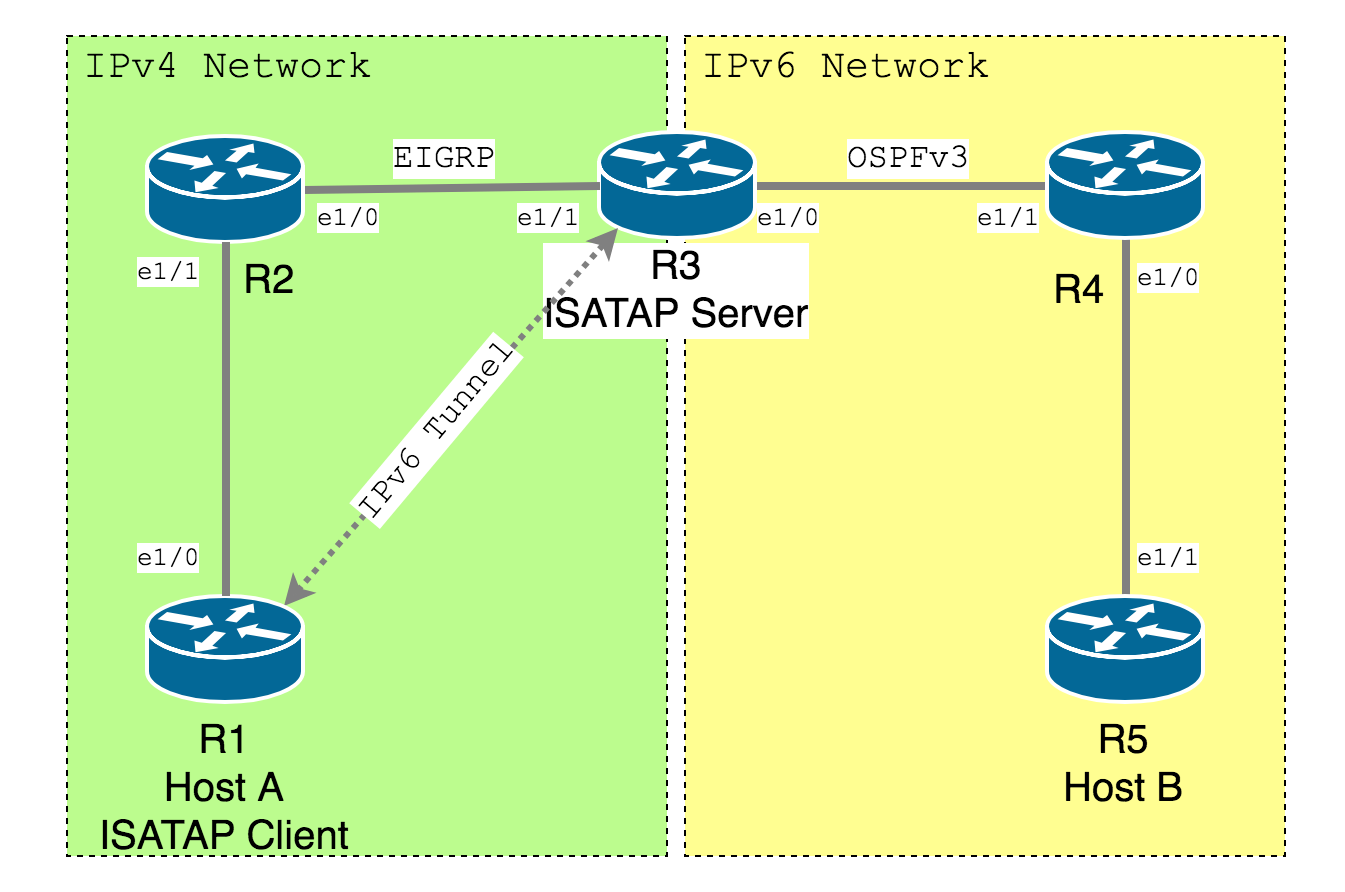
R2 与 R3 跑 EIGRP,让 Host A 可以与 ISATAP Server 通过 IPv4 通信。

R2
1
2
3
4
5
6
7
8
9
10
11
hostname R2
!
interface Ethernet1/0
ip address 192.168.23.2 255.255.255.0
!
interface Ethernet1/1
ip address 192.168.12.2 255.255.255.0
!
router eigrp 1
network 192.168.12.0
network 192.168.23.0

R3 是 ISATAP Server,作为中介的角色,连接 IPv4 与 IPv6 网络。

R3
1
2
3
4
5
6
7
8
9
10
11
12
13
14
15
16
hostname R3
!
ipv6 unicast-routing
!
interface Ethernet1/0
ipv6 address 2001:DB8:34::3/64
ipv6 ospf 1 area 0
!
interface Ethernet1/1
ip address 192.168.23.3 255.255.255.0
!
router eigrp 1
network 192.168.23.0
!
ipv6 router ospf 1
router-id 3.3.3.3

R3 与 R4 跑 OSPFv3。

R4
1
2
3
4
5
6
7
8
9
10
11
12
13
14
hostname R4
!
ipv6 unicast-routing
!
interface Ethernet1/0
ipv6 address 2001:DB8:45::4/64
ipv6 ospf 1 area 0
!
interface Ethernet1/1
ipv6 address 2001:DB8:34::4/64
ipv6 ospf 1 area 0
!
ipv6 router ospf 1
router-id 4.4.4.4

R5 只有 IPv6 Address。

R5
1
2
3
4
hostname R5
!
interface Ethernet1/1
ipv6 address 2001:DB8:45::5/64

基于 SLACC,R5 收到从 R4 发的 RA Default Route。

R5
1
2
3
4
5
6
7
8
9
10
11
12
13
14
15
16
R5#show ipv6 route
IPv6 Routing Table - default - 4 entries
Codes: C - Connected, L - Local, S - Static, U - Per-user Static route
B - BGP, R - RIP, H - NHRP, I1 - ISIS L1
I2 - ISIS L2, IA - ISIS interarea, IS - ISIS summary, D - EIGRP
EX - EIGRP external, ND - ND Default, NDp - ND Prefix, DCE - Destination
NDr - Redirect, O - OSPF Intra, OI - OSPF Inter, OE1 - OSPF ext 1
OE2 - OSPF ext 2, ON1 - OSPF NSSA ext 1, ON2 - OSPF NSSA ext 2, l - LISP
ND ::/0 [2/0]
via FE80::C804:16FF:FE0B:1C, Ethernet1/1
C 2001:DB8:45::/64 [0/0]
via Ethernet1/1, directly connected
L 2001:DB8:45::5/128 [0/0]
via Ethernet1/1, receive
L FF00::/8 [0/0]
via Null0, receive

现在 Host A (R1) 希望 Ping 通 R5,首先在 ISATAP Server (R3) 设定 Tunnel。

R3
1
2
3
4
5
R3(config)#int tunnel 0
R3(config-if)#ipv6 address 2001:DB8:3::3/64 // 设 IPv6 Address
R3(config-if)#ipv6 ospf 1 area 0 // 让此 Interface 的网段在 OSPFv3 发布
R3(config-if)#tunnel source 192.168.23.3 // 只需设 Tunnel Source,不必设 Tunnel Destination
R3(config-if)#tunnel mode ipv6ip isatap // 设定 Tunnel Mode 为 ISATAP

在 ISATAP Client (R1) 设定 Tunnel。

R1
1
2
3
4
5
R1(config)#int tunnel 0
R1(config-if)#ipv6 address autoconfig // 自动从 ISATAP Server 取得 IPv6 Address
R1(config-if)#tunnel source 192.168.12.1 // 设定 Tunnel Source
R1(config-if)#tunnel destination 192.168.23.3 // Tunnel Destinatin 为 ISATAP Server IP Address
R1(config-if)#tunnel mode ipv6ip // 留意 Client 不需要 ISATAP keyword

于是,R1 会从 R3 取得 IPv6 Address,并得到一条 IPv6 Default Route。

R1
1
2
3
4
5
6
7
8
9
10
11
12
13
14
15
16
R1#show ipv6 route
IPv6 Routing Table - default - 4 entries
Codes: C - Connected, L - Local, S - Static, U - Per-user Static route
B - BGP, R - RIP, H - NHRP, I1 - ISIS L1
I2 - ISIS L2, IA - ISIS interarea, IS - ISIS summary, D - EIGRP
EX - EIGRP external, ND - ND Default, NDp - ND Prefix, DCE - Destination
NDr - Redirect, O - OSPF Intra, OI - OSPF Inter, OE1 - OSPF ext 1
OE2 - OSPF ext 2, ON1 - OSPF NSSA ext 1, ON2 - OSPF NSSA ext 2, l - LISP
ND ::/0 [2/0]
via FE80::5EFE:C0A8:1703, Tunnel0
NDp 2001:DB8:3::/64 [2/0]
via Tunnel0, directly connected
L 2001:DB8:3::C0A8:C01/128 [0/0]
via Tunnel0, receive
L FF00::/8 [0/0]
via Null0, receive
R1
1
2
3
4
5
R1#ping 2001:DB8:45::5
Type escape sequence to abort.
Sending 5, 100-byte ICMP Echos to 2001:DB8:45::5, timeout is 2 seconds:
!!!!!
Success rate is 100 percent (5/5), round-trip min/avg/max = 48/55/60 ms

从 Traceroute 可见 Client 直接连到 ISATAP Server,通过 Server 连到 IPv6 Network。

R1
1
2
3
4
5
6
7
R1#traceroute 2001:db8:45::5
Type escape sequence to abort.
Tracing the route to 2001:DB8:45::5

1 2001:DB8:3::3 36 msec 28 msec 32 msec
2 2001:DB8:34::4 40 msec 40 msec 40 msec
3 2001:DB8:45::5 52 msec 52 msec 48 msec

除 Cisco IOS,现在大部份 OS 包括 Windows、Linux 和 MacOS (要安装 ISATAP Client) 都支持了 ISATAP。

6to4 Tunnel

ISATAP 比较适合单机连接 IPv6 网络。但如果希望把两个 IPv6 Network 通过 IPv4 连接起来 (即 Site to Site 架构),则 6to4 Tunnel 比较适合。

图中 IPv4 Network 以 OSPF 打通, 先在 R2 和 R4 建立 Tunnel。

特别要说的是,建立 6to4 Tunnel Interface 的 IPv6 Address 需要和 Source Interface 对应。

例如:R2 的 Source Interface 192.168.23.2 转换成 16 进数,即 C0A8:1702,再加上 IPv6 Tunnel 专用的 Prefix 2002::/16,整个 Tunnel IPv6 Address 将会是 2002:C0A8:1702::/48

R2
1
2
3
4
5
R2
interface Tunnel0
ipv6 address 2002:C0A8:1702::/48
tunnel source 192.168.23.2
tunnel mode ipv6ip 6to4
R4
1
2
3
4
5
R4
interface Tunnel0
ipv6 address 2002:C0A8:2204::/48
tunnel source 192.168.34.4
tunnel mode ipv6ip 6to4

然后要在建立 Tunnel 的 Route 分别加上两条 IPv6 Static Route,第一条是把对家 Tunnel Interface IP 指向 Tunnel 0,第二条是把对家 Network 指向对家 Tunnel Interface IP。

R2
1
2
R2(config)#ipv6 route 2002:C0A8:2204::/48 Tunnel0
R2(config)#ipv6 route 2001:DB8:45::/64 2002:C0A8:2204::
R4
1
2
R4(config)#ipv6 route 2002:C0A8:1702::/48 Tunnel0
R4(cofnig)#ipv6 route 2001:DB8:12::/64 2002:C0A8:1702::
R1
1
2
3
4
5
R1#ping 2001:db8:45::5
Type escape sequence to abort.
Sending 5, 100-byte ICMP Echos to 2001:DB8:45::5, timeout is 2 seconds:
!!!!!
Success rate is 100 percent (5/5), round-trip min/avg/max = 48/52/64 ms
Author

Jason

Posted on

09/06/18

Updated on

10/01/21

Licensed under

Comments

Your browser is out-of-date!

Update your browser to view this website correctly.&npsb;Update my browser now

×